
RECORDING BALL KICKING FOR PERFORMANCE ANALYSIS
Introduction
The primary purpose of this structured recording setup is to enable the extraction of motion data from performance. The kicking action is captured in a clear and organized manner so that measurable information can be derived from the recorded movement. When camera positions, heights, and distances are carefully defined, the footage becomes suitable for analyzing body mechanics, movement phases, timing, ball trajectory, and accuracy.
By maintaining a consistent recording environment, each attempt is captured under the same spatial conditions. This consistency ensures that the extracted motion data are reliable and comparable across trials. The configuration presented in this article is practical and repeatable, creating a structured foundation for collecting performance-based data and integrating it into the teaching process.
Using this setup, motion data were extracted and presented in separate sections addressing the approach to the ball (LINK), the ball contact phase (LINK), and the ball trajectory with target accuracy (LINK). Together, these components form a structured analytical framework for understanding and systematically improving kicking performance in youth players.
Content Overview
1. Defined Recording Zone and Setup of Markers
2. Camera Setup and Geometric Alignment
3. 3D Simulation of the Recording Setup
4. Camera Views and Frame Outputs
5. Conclusion
1.Defined Recording Zone and Setup of Markers
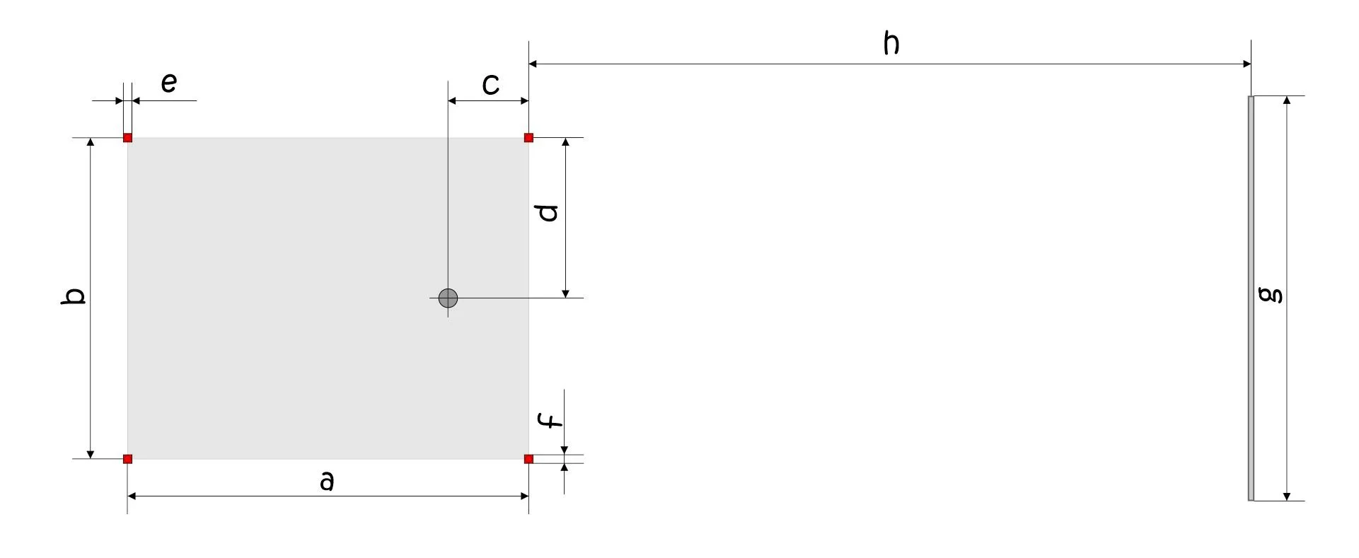
A defined recording zone is essential for extracting measurable distance data from video footage. The marked area shown in the technical drawings attached below establishes fixed spatial reference points that allow pixel measurements in the video to be converted into real-world distances.
Visual 01
The rectangular recording field (dimensions a × b) creates a controlled performance area. The corner markers function as calibration reference points. Because the true distances between these markers are known, they provide a scaling framework for motion analysis. Any displacement observed in the video—such as approach steps, ball movement, or body positioning—can be calculated relative to these predefined measurements.
Visual 02
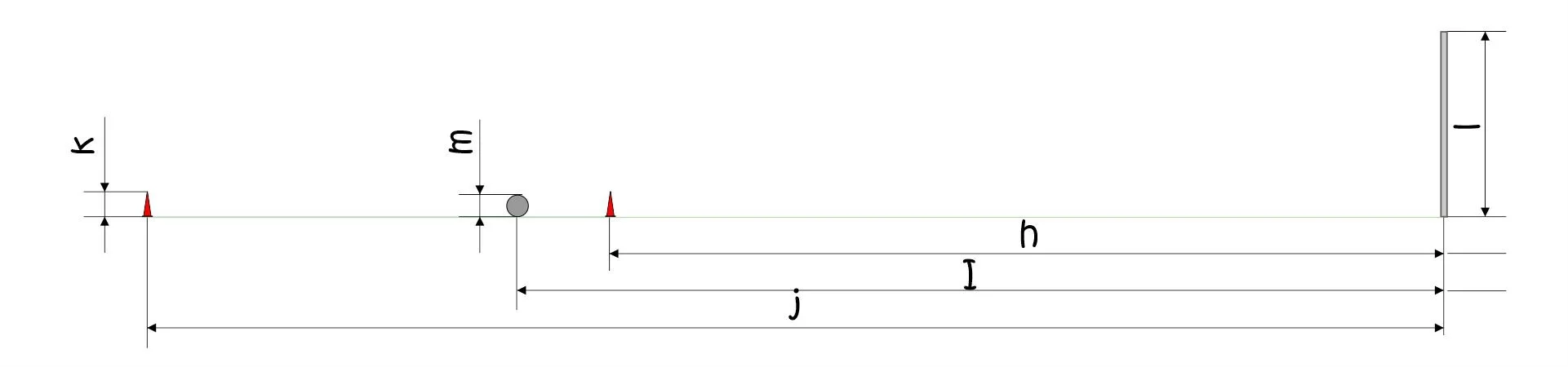
Additional longitudinal measurements (h, j, I) define the distance between the kicking zone and the target. These distances enable calculations such as ball travel distance, estimation of initial ball velocity (when combined with time data), and accuracy relative to the target position..
Visual 03
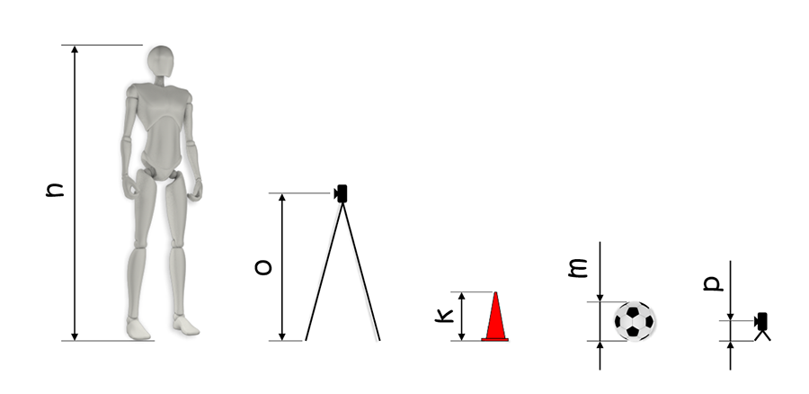
The vertical dimensions (k, m, o, p, etc.) define object heights and camera height. These parameters are important for minimizing perspective distortion and improving the accuracy of ball trajectory and body alignment analysis.
For basic calculation, only a limited number of core parameters are required. The fundamental dimensions are a × b (recording zone size), h (distance to target), and m (ball height reference). Based on these primary measurements, additional spatial relationships can be derived mathematically. However, when more parameters from the setup are known and measured precisely, the accuracy of the calculations increases significantly. Without clearly measured distances in the physical setup, video analysis remains observational. With defined and known dimensions, the recording becomes quantifiable.
By establishing a measured recording zone with documented spatial parameters, the setup transforms standard video capture into a structured data collection system suitable for educational analysis and performance evaluation.
2. Camera Setup and Geometric Alignment
By integrating measured spatial parameters with geometrically aligned camera positions, the recording system functions as a calibrated measurement environment rather than a simple video capture arrangement. For this reason, cameras must be positioned according to a defined spatial logic, not convenience.
Visual 04
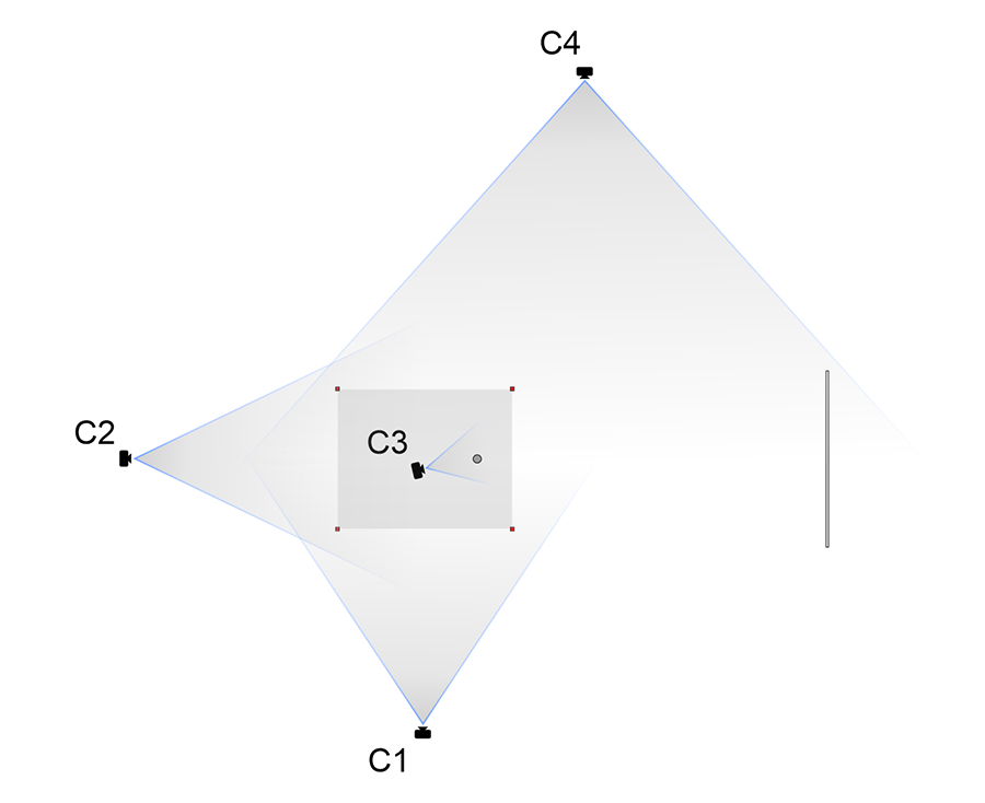
Visual 04 illustrates the spatial coverage of the four-camera configuration (C1, C2, C3, C4). Each camera captures the defined recording zone from a distinct perspective. The overlapping fields of view ensure that the kicking action, ball contact phase, and ball trajectory remain fully visible throughout the performance.
Precise camera alignment and documented distances relative to the field markers become essential when high-accuracy motion data extraction is the objective. In contrast, when the purpose is general observational feedback, strict geometric calibration is less critical.
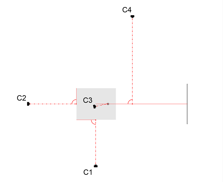
Visual 05
Visual 05 presents the geometric alignment of the system. The dashed reference lines indicate the central longitudinal and transverse axes of the recording zone, as well as their perpendicular relationships. These axes establish the spatial framework necessary for accurate measurement.
Stable tripod positioning is mandatory to prevent displacement during recording. The right-angle relationships shown in the visual reduce perspective distortion and improve the accuracy of converting pixel displacement into real-world distances. When camera geometry is controlled and spatial parameters are documented, the recording setup becomes a reliable analytical tool suitable for structured educational and performance evaluation purposes.
3. 3D Simulation of the Recording Setup
The 3D simulation is designed to help teachers and students clearly understand how the recording session will appear before it takes place. It provides a comprehensive visual representation of the entire recording arrangement, allowing the activity to be organized in advance. This preparation saves time and effort by ensuring that all elements are properly positioned before the recording is executed.
Visual 06
The model presents the defined recording zone, the position of the player and ball, the location of the target, and the placement of all cameras. These elements correspond directly to the previously presented 2D technical visuals. By integrating them into a single three-dimensional view, the simulation clarifies the spatial relationships between all components of the system.
Through this unified representation, teachers can verify camera placement, spatial distances, and performance direction prior to the session. Students can visualize the boundaries of the recording area and better understand the organization of the task.
In this way, the 3D simulation functions as both a planning and instructional tool. It ensures that the recording process is structured, efficient, and prepared for subsequent motion data extraction and educational application.
4. Camera Views and Frame Outputs
The previously presented recording setup produces four complementary views of the kicking performance. Each camera captures a different perspective of the same action within the calibrated recording zone. These views are presented in the visual below.
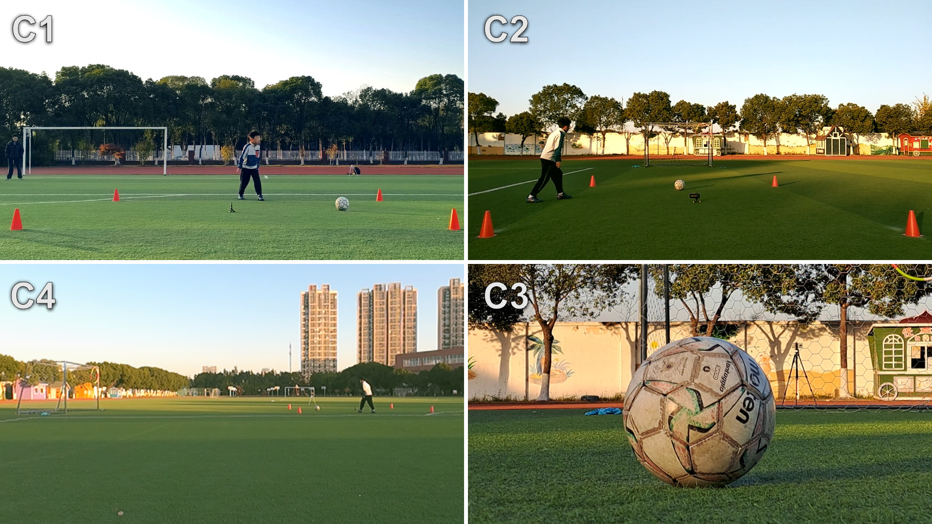
Visual 07
• C1 provides a side view of the player’s approach toward the ball.
• C2 captures the rear view of the player during the approach phase.
• C3 presents a close rear view of the ball and the contact phase.
• C4 records the longitudinal trajectory of the ball toward the target.
Together, these synchronized views demonstrate how the structured recording setup translates into measurable visual outputs, forming the basis for subsequent motion data extraction.
5. Conclusion
A structured recording setup transforms standard video capture into a purposeful data collection system. By defining the recording zone, measuring key spatial parameters, aligning cameras geometrically, and organizing multi-angle views, performance can be documented in a consistent and analyzable manner.
This approach enables systematic extraction of motion data and its direct integration into teaching practice. As a result, the recording process supports objective performance evaluation and provides a stronger foundation for instructional decision-making in youth player development.